Watch Movement Parts Tray Photos: A Practical Guide for Searchable Repair Records
Learn how to photograph, clean, label, compress, and archive watch movement parts tray images so repair records remain readable, searchable, and useful.
Watch Movement Parts Tray Photos: A Practical Guide for Searchable Repair Records
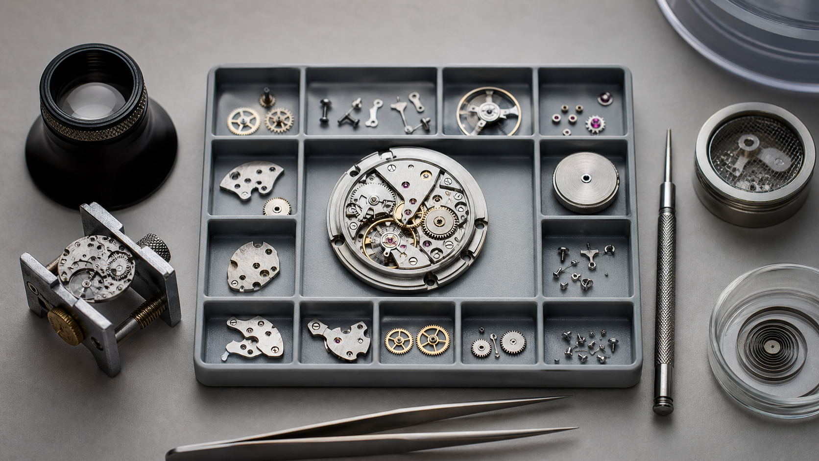
A tray of disassembled watch parts can look perfectly organized at the bench and become surprisingly difficult to interpret six months later. A wide phone photo may prove that the movement was taken apart, but it often fails to show which screw belonged to which bridge, whether a jewel was already cracked, or how a spring was oriented before cleaning.
This matters whenever a repair pauses, changes hands, requires customer approval, or returns with a later fault. Good tray photographs create a compact visual record of the movement at specific stages. They can support estimates, reassembly, parts sourcing, training, and dispute resolution without turning every repair into a full studio production.
The goal is not to make decorative watch photography. It is to produce images that answer practical questions quickly. That requires deliberate tray organization, consistent camera placement, controlled light, careful file handling, and a small amount of editing that improves evidence without altering it.
Decide What the Record Must Prove
Start by defining the purpose of the photographs. A record intended only as a reassembly aid can be simpler than one used for customer communication or condition reporting.
Common purposes include:
- Showing the complete movement and all removed components at intake.
- Preserving the location and orientation of parts during disassembly.
- Recording corrosion, scoring, broken pivots, cracked jewels, and prior repair marks.
- Linking replacement parts to a particular job.
- Documenting the state of components before and after cleaning.
- Giving another watchmaker enough context to continue a paused repair.
- Producing a concise PDF attachment for an estimate or service report.
Write down the two or three questions that a future viewer will most likely ask. For example: Was the click spring present? Which train wheel showed damaged teeth? Were the case screws already mismatched? Those questions determine which views and details you need.
Do not rely on a single photograph to satisfy every purpose. A wide image provides context, while a close image provides evidence. Trying to obtain both from one extremely high-resolution frame usually creates awkward crops, inconsistent scale, and overlooked blind spots.
Organize the Tray Before Taking Photographs
Image quality cannot rescue an ambiguous tray. Components that overlap, loose screws scattered across several wells, and reflections from oily surfaces all make later interpretation harder.
Use a clean tray with shallow compartments and a matte, contrasting surface. Pale gray or muted blue usually works well with steel, brass, and ruby-colored jewels. Pure white can cause glare, while black may hide dark screws and polished edges.
Group parts by assembly or removal stage rather than merely by size. A useful sequence might separate the automatic winding system, balance assembly, keyless works, train, barrel, calendar components, and casing parts. Keep paired or interacting components close together, but avoid contact that could scratch polished surfaces.
Before photographing, check that:
- Every loose screw is fully inside a compartment.
- No wheel is resting on its pivot.
- Springs are visible rather than concealed beneath larger components.
- Similar screws are separated when their positions matter.
- Components do not overlap identifying features.
- Fibers, pegwood fragments, and unrelated bench debris have been removed.
- Any temporary covers do not obscure the parts being documented.
For very small items, use separate micro-containers inside the tray. Transparent lids can prevent loss, but photograph reflective containers both closed and open if the contents are important.
Build a Repeatable Capture Station
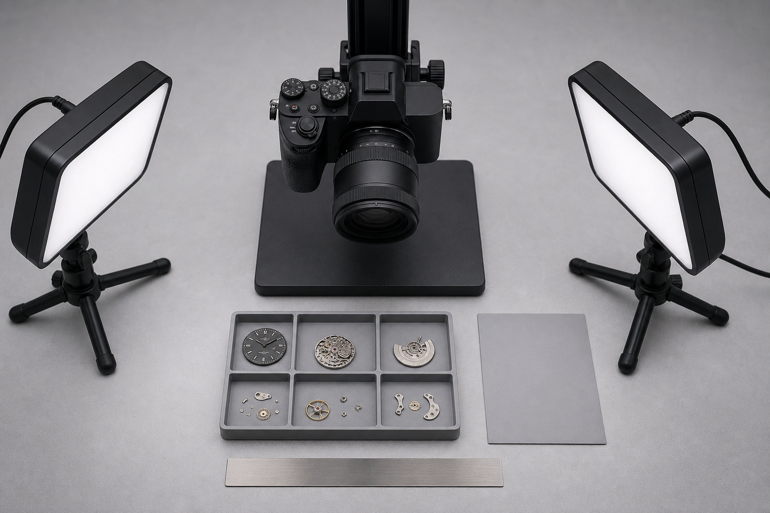
Consistency is more valuable than an elaborate camera. A modest camera or recent phone can produce useful records when its position, lighting, and distance remain stable.
Mount the camera directly above the tray whenever possible. A copy stand, articulated bench arm, or rigid overhead phone holder prevents perspective distortion and makes repeated images easier to compare. Align the sensor plane parallel to the tray rather than correcting a steep angle afterward.
Place two diffused lights on opposite sides of the tray at approximately 45 degrees. This reduces deep shadows while retaining enough surface modeling to reveal scratches and damaged teeth. Avoid a bare ring light as the only source; it can create circular highlights on polished bridges and flatten shallow defects.
Set the station so it can be restored quickly. Mark the tray position on the bench mat and note the approximate camera height. If the camera application permits manual controls, lock exposure, white balance, and focus after testing them. Automatic settings may shift dramatically when a large brass plate is replaced by a mostly empty gray tray.
A basic capture setup should include:
- A rigid overhead mount.
- Two diffused, color-matched lights.
- A plain matte background.
- A small neutral reference card.
- A nonreflective scale or ruler for damage views.
- A blower and clean brush for removing visible debris.
Check the first image at full size before continuing. Confirm that the smallest important screws have defined edges and that polished parts are not clipped to featureless white.
Control Reflections Without Hiding Surface Damage
Watch components are difficult subjects because they combine polished steel, brushed plates, brass wheels, jewels, oil, and dark recesses. A lighting arrangement that makes one part clear may obscure another.
Large diffusers are usually more effective than stronger lamps. Move the diffusion material closer to the tray to enlarge the apparent light source. If a bridge produces a bright rectangular reflection, change the lamp angle slightly rather than underexposing the entire image.
A circular polarizing filter can reduce some glare, especially from plastic trays and protective covers. It will not eliminate every reflection from metal, and excessive polarization can suppress the sheen that reveals scratches or uneven finishing. Treat it as a controlled adjustment, not an automatic cure.
For defects, take two images with slightly different light directions. A scratch, dent, or bent tooth may appear in one and vanish in the other. Keep both when the lighting difference carries meaningful evidence.
Create an Image Set That Answers Repair Questions
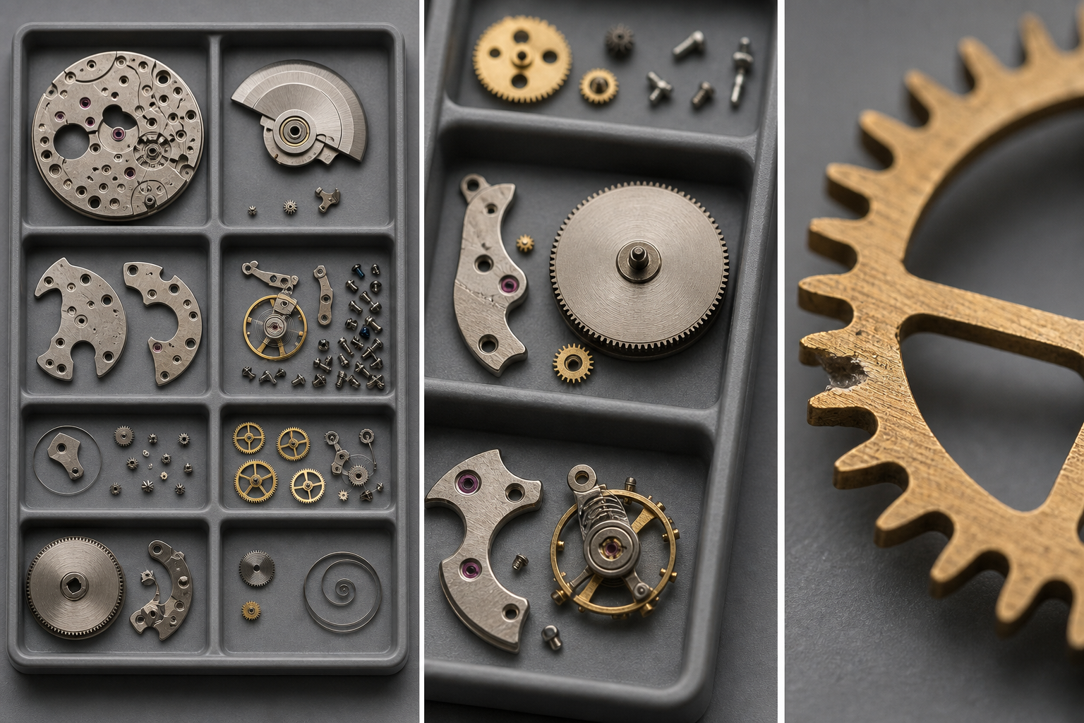
A compact record normally needs three levels of coverage: context, assembly groups, and defects.
1. The complete tray view
Photograph the entire tray from directly above. Include all occupied compartments and enough tray boundary to establish orientation. This is the index image for the repair.
Do not crop so tightly that the viewer cannot tell which row or corner is shown. If a job number is physically included, place it beside the tray rather than over components. Avoid exposing customer names, addresses, or telephone numbers in images that may later be shared.
2. The compartment or assembly views
Create closer images for dense groups such as calendar works or the keyless mechanism. Preserve some neighboring compartments in the frame so the crop retains location context.
Use the same direction for every assembly view. Rotating the tray between photographs creates avoidable uncertainty, particularly when similar screws occupy mirrored positions.
3. The macro defect views
Photograph each significant defect separately. Include one image that establishes where the defect is located and another that shows its detail. When size matters, add a scale in the same plane as the component.
Macro views should record observable facts, not imply a diagnosis the image cannot prove. A caption such as “irregular surface visible on third wheel pivot” is safer than “pivot ruined by incorrect oil” unless other inspection supports that conclusion.
Recommended coverage by situation
| Situation | Minimum useful images | Additional evidence |
|---|---|---|
| Routine service | One complete tray view, two assembly views | Final movement and timing-machine screen |
| Repair paused overnight | One complete tray view | Close view of the active assembly |
| Customer estimate | Complete movement, complete tray, each billable defect | Scale view and alternate light angle |
| Parts sourcing | Full component, mounting area, damaged detail | Measurements and caliber markings |
| Handover to another repairer | Complete tray plus every assembly group | Notes showing current service stage |
| Before-and-after comparison | Matched views at both stages | Consistent light, scale, and orientation |
This set is usually more useful than dozens of nearly identical frames. Extra images increase review time and make important evidence harder to locate.
Use Identifiers Without Covering Components
Every file must remain associated with the correct repair after it leaves the camera roll. A visually perfect photograph named IMG_4827.jpg is fragile evidence.
Use a non-sensitive repair identifier, capture stage, view type, and sequence number. A practical pattern is:
R1842_disassembly_tray_01.jpg
R1842_disassembly_keyless_02.jpg
R1842_defect_escape-wheel_03.jpg
Keep the identifier short enough to remain readable in file browsers. Use the same vocabulary across jobs: intake, disassembly, defect, cleaned, reassembly, and final are easier to filter than improvised descriptions.
A small physical job card can appear at the edge of the first image, but filenames should still carry the identifier. Cards may be cropped away, obscured in thumbnails, or rendered unreadable after compression.
If a card contains printed details that need to become searchable notes, crop it separately and process it with an image OCR tool. Verify every recognized caliber number, serial fragment, and part reference manually. OCR commonly confuses zero with the letter O, one with I, and five with S—exactly the errors that can misdirect a parts search.
Edit for Clarity Without Changing Evidence
Repair documentation should be improved conservatively. Cropping, rotation, mild exposure correction, and neutral color adjustment are usually appropriate. Removing a scratch, recreating a broken tooth, or using generative fill around a damaged area is not.
Begin by keeping the untouched original. Create edited derivatives rather than overwriting the capture. The original protects context and allows later reviewers to check whether an adjustment concealed information.
A safe editing sequence is:
- Correct rotation and perspective.
- Crop distracting bench space while retaining tray orientation.
- Adjust white balance using the neutral reference.
- Lift exposure slightly if dark components lack separation.
- Reduce highlights only enough to recover visible metal detail.
- Apply modest sharpening at the final output size.
- Inspect the edited image at 100 percent.
The AI photo editor can help with general exposure, background distractions, or preparing a clearly marked presentation copy. For evidentiary repair records, avoid any operation that invents pixels near a component or defect. If a background is cleaned for a customer-facing image, retain the documentary version separately.
Color accuracy matters most when color supports a finding, such as oxidation, residue, heat tint, or jewel condition. Avoid dramatic saturation and contrast. A technically neutral image may look less impressive but communicate more faithfully.
Resize According to the Smallest Required Detail
Do not select image dimensions by habit. Determine what the viewer must inspect after export.
A full-tray overview often remains useful at 2000 to 3000 pixels on its long edge. A macro image of a jewel setting may need similar dimensions even though it covers a much smaller physical area. Tiny details disappear when a high-resolution source is reduced too aggressively.
Use the image resizer to create consistent delivery copies while preserving full-resolution originals. Resize only after cropping; otherwise, you may discard pixels that a later crop needs.
Test the actual viewing condition. Open the exported image on the laptop or tablet normally used at the bench. If identifying a screw slot requires extreme zooming, either retain a larger export or add a closer photograph.
Compress Files Without Erasing Fine Metal Edges
Watch components punish heavy JPEG compression. Thin spokes, gear teeth, engraved caliber marks, screw slots, and jewel boundaries can acquire halos or block-like artifacts.
For most photographic records, a high-quality JPEG offers a sensible balance. PNG can preserve crisp edges but often produces unnecessarily large files for detailed photographs. WebP may be efficient for browser-based records, but confirm that every system receiving the files supports it.
Use the image compressor on delivery copies and compare the result with the uncompressed edit. Examine these areas at full size:
- The teeth of the smallest wheel.
- Fine scratches on polished steel.
- Edges around red jewels.
- Engraved or stamped characters.
- Dark screw slots against bright heads.
- Coiled springs and other thin curved forms.
If artifacts are visible, reduce compression or export the critical macro separately at higher quality. Saving a few hundred kilobytes is not worthwhile if the file no longer supports the repair decision.
Assemble a Compact Repair PDF
A PDF can make a small image set easier to review, send, and archive. It should complement the original image folder, not replace it.
Arrange the document in the same order a reviewer would investigate the job:
- Repair identifier and non-sensitive watch description.
- Intake or complete-movement view.
- Complete tray view.
- Assembly-group views.
- Defect views with short factual captions.
- Cleaned or replacement-part views, when relevant.
- Final assembled condition.
Use one large image per page for intricate defects. Two or four images per page can work for broad assembly views, provided the parts remain legible at normal zoom. Avoid squeezing twelve macro photographs onto a contact sheet merely to reduce page count.
The image-to-PDF tool can turn the ordered delivery images into a review packet. If intake paperwork, timing results, or an estimate already exist as separate PDFs, combine them with the PDF merge tool. Check the merged file page by page because mixed portrait and landscape pages can produce unexpected rotation or scaling.
Keep captions concise and observable. Include component name, location, service stage, and the visible condition. Put interpretation in the written repair notes when it requires evidence beyond the photograph.
Protect Privacy and Preserve Traceability
A repair archive can contain customer details, serial numbers, warranty information, and recognizable high-value watches. Decide who needs access before sharing an image set.
Crop customer paperwork from bench photographs. Use job identifiers instead of names in filenames. If a case serial is not relevant to the recipient, provide a separate presentation copy in which that area is excluded rather than altering the master record.
Preserve traceability with a simple folder structure:
originalsfor untouched camera files.edited-recordsfor documentary corrections.deliveryfor resized and compressed copies.reportfor the assembled PDF and supporting notes.
Back up the record according to the shop's retention policy. Cloud synchronization alone is not necessarily a backup if deletion immediately propagates to every device. At least one protected copy should retain prior versions or remain separate from the active folder.
Run a Final Record Audit
Before closing the job folder, review it as if you had never seen the movement. The following audit catches most documentation failures:
- The repair identifier is present in filenames and notes.
- The complete tray is visible in at least one sharp image.
- Tray orientation remains consistent across closer views.
- Important components do not overlap.
- Every documented defect has both context and detail.
- Reflections do not conceal the relevant surface.
- Scale is included where physical size matters.
- Editing has not removed or reconstructed evidence.
- Full-resolution originals remain untouched.
- Delivery images are readable at normal viewing size.
- Compression has not damaged gear teeth, engravings, or springs.
- Customer details are absent from externally shared copies.
- The PDF opens correctly and follows the repair sequence.
- A second person could understand the current service stage.
If the last point fails, add a short note rather than taking more photographs without a clear purpose. Images show condition and location well; they are less reliable at communicating intent, diagnosis, or the next action.
Make the Record Useful at the Bench
The best parts tray record is neither the largest nor the most polished. It is the one a watchmaker can open months later and understand within a minute.
Consistency does most of the work. Use the same tray orientation, capture station, naming terms, editing limits, and folder structure for every repair. Add close views only when they answer a specific question. Preserve originals, and keep presentation edits separate from documentary evidence.
Once those habits are established, photography stops being an interruption and becomes a practical extension of bench discipline. A few carefully planned images can preserve component relationships, expose the history of a defect, simplify handovers, and make a repair record substantially more valuable than a folder of anonymous phone photographs.