PCB Silkscreen Photo Cleanup for Repair Notes and Parts Records
Turn difficult circuit-board photos into readable repair evidence with controlled lighting, perspective correction, careful enhancement, OCR checks, and compact PDF records.
PCB Silkscreen Photo Cleanup for Repair Notes and Parts Records
A circuit-board photograph often has to do several jobs at once. It may document the board before disassembly, preserve connector orientation, capture jumper locations, identify a revision, and record the markings on components that might later be removed. Unfortunately, the photograph that proves where a capacitor was installed is not always the photograph from which a technician can read its value.
Populated printed circuit boards are unusually difficult subjects. Glossy solder mask creates reflections, tall components cast shadows, white silkscreen runs beneath parts, and tiny laser markings may have less contrast than the copper traces below them. Automatic enhancement can make the image look sharper while quietly changing characters. A damaged 8 can become a 3, or a faint C15 can be interpreted as C1S.
This guide presents a practical system for producing readable PCB photographs without treating automated recognition as an unquestionable source of truth. It is intended for repair shops, restoration hobbyists, makerspaces, small manufacturers, and anyone building searchable parts or service records from board photos.
Decide What the Photograph Must Prove
Before adjusting a camera or opening an editor, define the purpose of the record. A single attractive overview rarely captures every useful detail.
Typical objectives include:
- Recording the board revision and assembly number.
- Preserving connector, cable, and socket orientation.
- Reading reference designators such as R42, C18, U7, and J3.
- Recording integrated-circuit, transistor, relay, and crystal markings.
- Showing corrosion, overheating, cracked solder joints, or prior repairs.
- Mapping removed components back to their original positions.
- Creating a searchable attachment for a repair ticket or asset record.
Separate observed facts from conclusions. A photograph may clearly show U12, while the complete part marking remains uncertain. Record the reference designator as confirmed and the part number as unresolved instead of filling the gap from memory.
Create a short capture list before touching the board. For a routine repair, a useful set is:
- Full component-side overview.
- Full solder-side overview.
- Board identifier and revision close-up.
- Power-input and connector close-ups.
- Images of damaged or modified areas.
- Close-ups of parts whose markings matter.
- One final image after repair.
This list prevents the common discovery that the only photograph of an important area is blurred or hidden by a cable.
Stabilize the Board Before Photography
Disconnect all power sources and follow appropriate electrical-safety procedures for the equipment. Large capacitors and power supplies can retain hazardous energy. This article concerns documentation, not safe discharge or live diagnostic techniques.
Place the board on a clean, stable, static-conscious surface suitable for the device. Remove loose dust only when doing so is safe for the assembly. Do not aggressively clean corrosion, residue, labels, or heat damage before recording the original condition. Those features may be valuable evidence.
If cables must remain attached, support them so they do not pull the board upward. Use nonconductive supports outside the photographed area if the board rocks. Do not place an energized board on improvised conductive surfaces for the sake of a cleaner background.
Assign the item a temporary identifier before taking multiple images. The identifier can be written on a separate card positioned beside, rather than on, the board. Keep that card out of close-ups intended for OCR if its large characters could be confused with board markings.
Build a Repeatable Capture Station
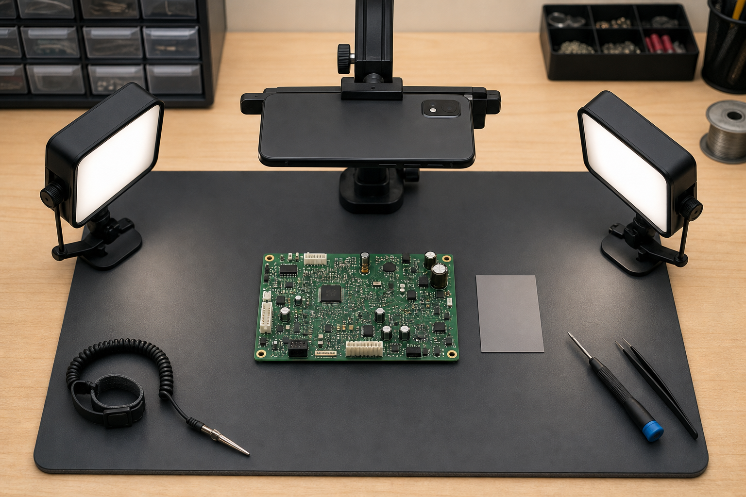
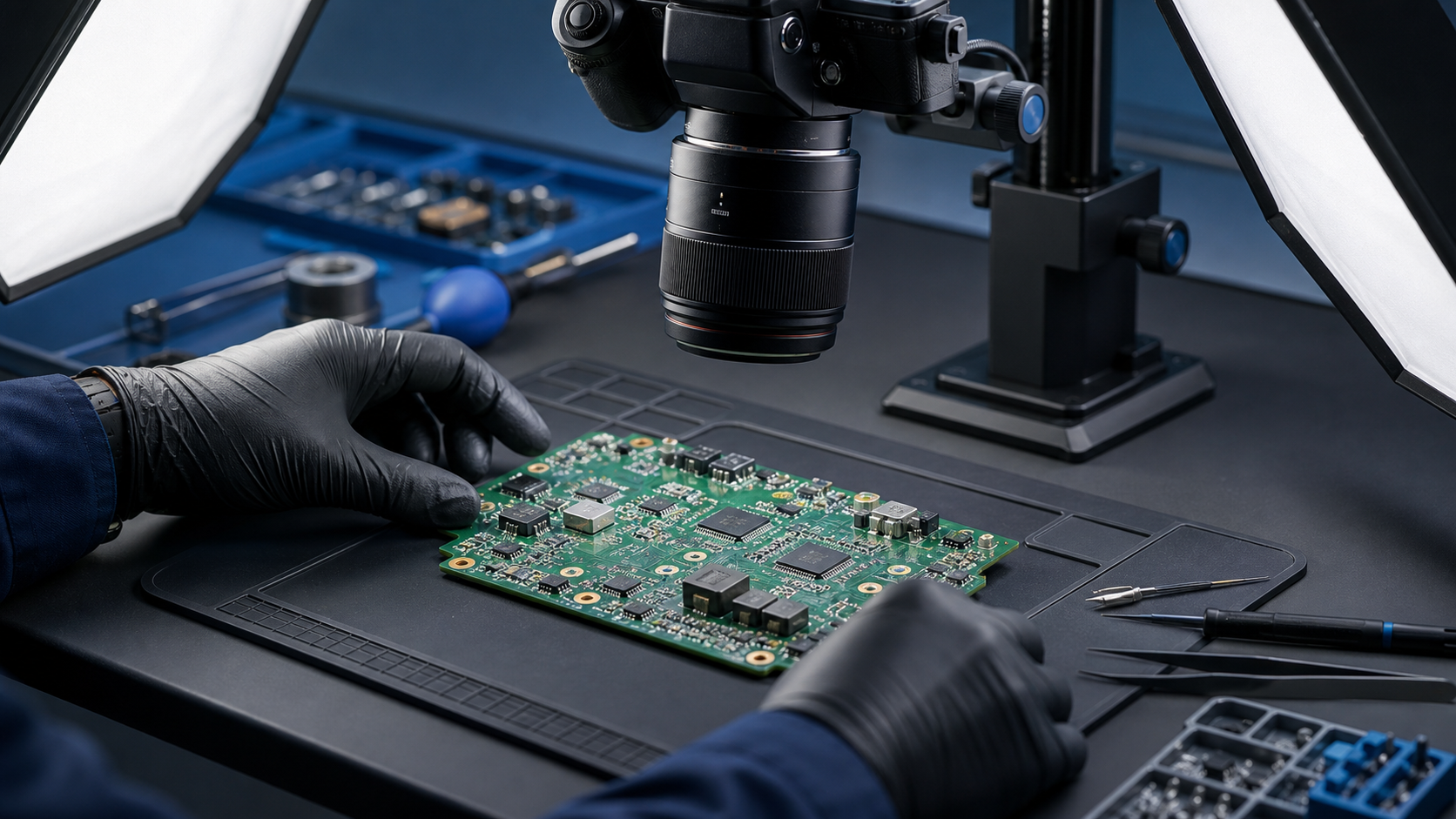
A useful capture station can be modest: a stable phone or camera support, two movable lights, diffusion material designed for photography, and a plain background. Repeatability matters more than decorative equipment.
Mount the camera so its sensor is as parallel to the board as possible. A tilted camera makes one edge soft, distorts component spacing, and turns rectangular labels into trapezoids. An overhead arm or copy stand is ideal, but a secure tripod with a horizontal extension can work.
Use two broad, diffused light sources on opposite sides. Start with both lights at approximately 30 to 45 degrees above the board. If the solder mask produces a bright stripe, move the lights laterally rather than increasing brightness. Broad sources create softer reflections than a bare desk lamp.
For glossy boards, cross-polarized photography can suppress reflections: polarizing film is placed over the lights, while a circular polarizer is fitted to the lens and rotated. This is useful but not mandatory. It also reduces available light, so the camera must remain stable for a slower exposure.
Choose a neutral, nonreflective background that contrasts with the board edge. Dark green boards are easier to isolate on gray than on black. Avoid patterned cutting mats in the primary overview because their grid can interfere with edge detection and visual inspection.
Capture Overview and Detail Images Separately
Do not rely on digital zoom into one wide photograph. An overview and a macro detail answer different questions.
For the overview, fill most of the frame while leaving a small border around the PCB. Keep the complete outline visible so orientation remains unambiguous. Capture both sides in the same orientation when practical. If the connector edge appears at the bottom on the component side, preserve that relationship when documenting the solder side, or explicitly note that the board was flipped.
For close-ups, move the camera closer or use an optical macro capability. Tap or manually focus on the printed marking, not the top of a nearby capacitor. Tall components can cause autofocus to choose the wrong plane.
Use the lowest practical ISO to reduce grain around fine characters. Stabilize the camera and use a timer or remote shutter. If a marking is critical, take three exposures:
- One with balanced lighting.
- One with light arriving from the left or right at a low angle.
- One slightly darker to protect pale printed characters from clipping.
Low-angle light can reveal laser etching, embossed package codes, and scratches that disappear under flat illumination. It can also exaggerate texture, so retain the balanced exposure as the neutral reference.
Include a scale in damage close-ups when dimensions matter, but keep it in the same plane as the feature. A ruler hovering above the board produces misleading measurements.
Preserve Originals Before Editing
Copy the original files into a case or repair folder before cropping, rotating, or enhancing anything. Treat these originals as evidence of what the camera captured.
A simple naming convention keeps related images together:
device-board-side-area-sequence-version.ext
For example:
radio-mainpcb-component-u12-01-original.jpg
Use stable terms such as component, solder, power, connector, and damage. Avoid filenames such as final2-new-reallyfinal.jpg, which provide no durable context.
If the camera produces HEIC or another format that your repair system cannot display, make a compatible derivative while retaining the source. The image converter can create a JPEG or PNG copy for broad compatibility. Conversion should not replace the untouched original.
Correct Orientation and Perspective First
Geometric correction belongs near the beginning because OCR and visual comparison both benefit from straight, consistently oriented text.
Rotate the image so the board identifier or dominant silkscreen reads naturally. Then correct perspective only if the board outline is visibly trapezoidal. Use known straight edges, mounting-hole rows, or connector lines as references. Do not force an irregularly shaped board into a rectangle.
Crop distractions but preserve enough surrounding context to show where the detail sits. A close crop of R17 is difficult to relocate if every neighboring component has been removed from view. For important markings, retain both a contextual crop and a tight reading crop.
Resize only after cropping. Enlarging an image does not recover characters that were never resolved by the camera. It may make inspection more comfortable, but it can also make interpolation artifacts look like real strokes. When a web form or repair platform imposes dimensions, use the image resizer on a derivative rather than the archival source.
Enhance Silkscreen Without Inventing Characters
PCB enhancement should make existing structure easier to inspect, not create a cosmetically dramatic image. Work from gentle, reversible adjustments.
Start with white balance. A strong green or blue cast can reduce the separation between white silkscreen and solder mask. Use a neutral object captured in the scene when available, but do not assume a white connector is spectrally neutral.
Next, set black and white points conservatively. Watch pale silkscreen strokes and shiny component tops. If they become featureless white patches, reduce highlights. Lift shadows only enough to reveal printed details beside tall parts; excessive shadow recovery amplifies noise.
Apply local contrast or clarity in small amounts. Heavy clarity creates bright and dark halos around every trace, making narrow characters harder to interpret. Moderate sharpening should be judged at 100 percent magnification. Stop when real edges become distinct, before grain and compression blocks acquire hard outlines.
Color channels can sometimes separate markings better than a normal grayscale conversion. White text on green solder mask may read more clearly when the green channel is darkened relative to red and blue. Compare channels rather than assuming desaturation is sufficient.
For isolated areas, the AI photo editor may help with controlled cleanup or tonal adjustments, but generated reconstruction should never be used to establish an uncertain part number. Keep any interpretive edit clearly separated from documentary originals.
Use a Two-Version Record Instead of One Overprocessed Image
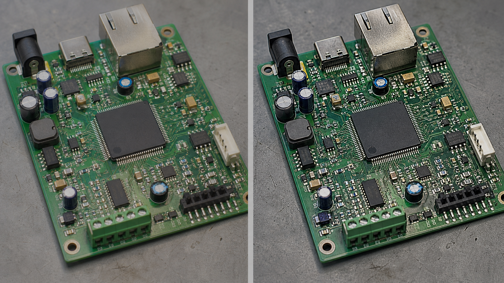
A strong repair record contains two complementary versions:
| Version | Primary purpose | Recommended treatment | Main risk |
|---|---|---|---|
| Natural reference | Condition, color, orientation, and physical context | White balance, rotation, mild exposure correction | Fine markings may remain faint |
| Reading copy | Silkscreen and component-mark inspection | Tight crop, grayscale or channel mix, moderate contrast and sharpening | Processing may alter ambiguous strokes |
The natural reference protects context. The reading copy supports inspection. Keeping both avoids the false choice between an authentic-looking photograph and a highly legible derivative.
Label derivative files in their filenames or associated notes. Terms such as reference, reading, grayscale, and contrast communicate what changed. Do not overwrite the reference with the reading copy.
For a very uncertain marking, create several restrained derivatives rather than one extreme version. A technician can compare the natural image, red-channel view, grayscale view, and low-angle exposure. Agreement across independent captures is more persuasive than aggressive processing of a single file.
Run OCR on Small, Purposeful Regions
Whole-board OCR usually produces a noisy mixture of reference designators, component markings, logos, certification symbols, and trace-like shapes. Crop by purpose before recognition.
Good OCR regions include:
- The board model and revision block.
- One integrated circuit and its immediate package area.
- A connector label row.
- A group of clearly exposed reference designators.
- A serial-number sticker photographed square-on.
Use the image OCR tool on these focused crops. If recognition fails, check capture quality before applying stronger filters. Blur, reflection, and insufficient pixel detail cannot be reliably repaired by thresholding.
OCR output is a lead, not a verified transcription. Compare every critical result against the image. Watch for common substitutions:
| Visual ambiguity | Possible OCR substitutions |
|---|---|
0 | O, D, or Q |
1 | I, L, or 7 |
5 | S or 6 |
8 | B or 3 |
C | G or 0 |
| Hyphen | Missing mark or underscore |
| Slash | 1, I, or omitted character |
Part numbers require particular caution because one character can identify a completely different device. Validate them using package style, manufacturer marking conventions, circuit location, and—when appropriate—authoritative datasheets. Never use a plausible internet search result as proof that an unclear character must have a certain value.
Handle Hidden and Damaged Markings Honestly
Some information cannot be recovered from the first photograph. A reference designator may be beneath a capacitor, a package marking may be sanded away, or corrosion may have removed the ink.
Use explicit status terms in the repair record:
- Confirmed: Every character is visually supported.
- Probable: The reading is strongly supported but one feature remains ambiguous.
- Partial: Only part of the marking is readable.
- Obscured: A component or coating blocks the view.
- Missing: The expected marking is no longer present.
- Not captured: The required angle or resolution was not photographed.
These labels are more valuable than silently completing a code. When a component is later removed as part of an authorized repair, photograph the newly exposed designator before cleaning or installing a replacement.
Do not remove labels, coatings, shields, or components merely to improve documentation unless that action is already justified by the repair procedure. The record should support the repair, not introduce additional risk.
Assemble a Compact Repair PDF
A PDF packet is useful when images and observations must travel with a repair ticket, customer handoff, or equipment history. Organize it in the order a future reader will investigate the board:
- Device and board identification.
- Component-side overview.
- Solder-side overview.
- Connector and cable orientation.
- Damage or symptom areas.
- Critical component markings.
- OCR transcription with confidence status.
- Post-repair condition.
Place one or two related images on each page at a size where markings remain inspectable. Avoid squeezing twelve macro photographs into a contact sheet if the PDF will be viewed on a laptop. Captions should state what is visible, where it is located, and whether an image is enhanced.
The image-to-PDF tool can combine selected derivatives into a portable record. Retain the separate full-resolution images because PDF creation may resample them, depending on the chosen settings and viewer.
When a ticket already has a PDF report, create a clearly named photo appendix and combine it with the report using PDF merge. Check page order, orientation, and legibility after merging.
Control File Size Without Erasing Evidence
Large camera files can make a repair record cumbersome, but indiscriminate compression damages exactly the features being preserved. Thin silkscreen strokes, dot-matrix labels, and laser-etched package codes are vulnerable to block artifacts.
Keep full-resolution originals outside the delivery PDF. For reference JPEGs, use moderate compression and inspect the smallest critical text at 100 percent. PNG may suit flat, tightly cropped diagrams or screenshots, but it is often unnecessarily large for ordinary camera photographs.
Use the image compressor to create sharing copies only after the edits and OCR checks are complete. Compare before and after versions around the faintest marking, not merely around large components. If a character changes shape, increase quality or preserve that detail as a separate high-resolution crop.
Final Quality-Control Checklist
Before closing the repair record, verify the complete set rather than judging images individually.
Capture checks
- Both board sides are present when accessible.
- The board outline and orientation are clear.
- Revision, model, and serial identifiers have dedicated close-ups.
- Critical markings are in focus and free of severe glare.
- Damage was recorded before cleaning or component replacement.
- Connector and cable positions can be reconstructed.
Editing checks
- Originals remain untouched.
- Perspective correction did not distort the board.
- Highlights retain pale silkscreen detail.
- Sharpening did not add halos or false strokes.
- Reading copies are distinguishable from natural references.
- No generative edit is being treated as documentary evidence.
Transcription checks
- OCR was run on focused regions rather than the entire board alone.
- Critical characters were checked against the photograph.
- Ambiguous results carry an explicit confidence status.
- Part numbers were not completed solely from search suggestions.
- Reference designators remain connected to their physical locations.
Delivery checks
- Filenames sort in a sensible sequence.
- The PDF opens correctly and pages are oriented consistently.
- Essential close-ups remain readable at normal viewing size.
- Full-resolution source images are retained separately.
- Sensitive serial numbers or customer identifiers are shared only with intended recipients.
Build Records for the Next Technician
The most useful PCB photograph is not necessarily the sharpest or most dramatic. It is the one that lets another person distinguish observation from interpretation, find the relevant location, and understand what changed during repair.
That standard favors controlled capture, restrained enhancement, small OCR regions, explicit uncertainty, and paired reference and reading images. It also makes future comparison easier. When the same device returns months later, a technician can determine whether corrosion spread, a replacement part moved, or a connector was reinstalled differently.
A few extra minutes spent photographing the board square-on, changing the light angle, and preserving an unedited source can prevent hours of uncertainty later. For electronics documentation, legibility matters—but traceability matters just as much.