3D Printer First-Layer Photo Sheets: A Practical Calibration Record Guide
Build consistent photo records of 3D printer first layers, preserve diagnostic detail, compare calibration changes, and assemble compact PDF sheets for future troubleshooting.
3D Printer First-Layer Photo Sheets: A Practical Calibration Record Guide
A first-layer calibration print lasts a few minutes, but the evidence it provides is often discarded almost immediately. The square is peeled from the build plate, examined under whatever light happens to be available, and dropped into a bin. When the same printer begins producing poor first layers two months later, there is no reliable reference for how a healthy result actually looked.
A structured photo sheet turns those disposable tests into useful maintenance records. It lets you compare nozzle offsets, bed regions, filament types, build surfaces, and changes made during troubleshooting. This is particularly useful in print farms, school labs, repair shops, and shared maker spaces, but it also helps anyone maintaining more than one printer.
The goal is not attractive product photography. It is consistent diagnostic imaging: the same framing, similar lighting, preserved surface detail, and enough metadata to explain what changed between samples.
What a First-Layer Photograph Can Reveal
A first layer contains several overlapping signals. Line spacing may indicate an incorrect nozzle offset. Uneven gloss can suggest that one region received more pressure than another. Gaps between adjacent lines may point to insufficient squish, low flow, a partially restricted nozzle, or a combination of factors. Raised ridges can appear when the nozzle is too close or when excess material has nowhere to go.
Photography cannot determine every cause by itself. A photograph does not measure actual nozzle height, confirm extrusion calibration, or prove that a build plate is flat. It is best treated as comparative evidence rather than an automatic diagnosis.
A useful image should make these features visible:
- Separation or bonding between adjacent extrusion lines
- Changes in surface gloss across the sample
- Torn, dragged, or buckled regions
- Thin areas where the build surface shows through
- Thick ridges produced between neighboring passes
- Contour quality around corners and direction changes
- Differences between the center and edges of the bed
- Contamination, fingerprints, or residue on the lower surface
Keep both sides of a removed test when possible. The upper face reveals line behavior and nozzle interaction, while the build-plate face can show texture transfer, gaps, and local adhesion differences.
Choose a Test That Produces Comparable Evidence
The most useful calibration record begins with a repeatable print. Random failed parts are worth documenting, but they are poor controlled references because their geometry, slicing settings, and bed positions vary.
Use a simple test that can be reproduced later. A single-layer square is easy to inspect and store. A five-point set of squares adds information about bed regions. A broad grid is useful when investigating mesh leveling, although it is harder to photograph at high detail.
Record the source or version of the model. Small revisions can change line orientation, dimensions, or perimeter behavior. If the slicer generates the test procedurally, save the project file or document the relevant settings.
For meaningful comparisons, keep these variables stable unless one of them is deliberately under test:
- Model geometry and orientation
- Slicer version and profile
- Layer height and first-layer line width
- Nozzle diameter
- Print speed
- Bed and nozzle temperatures
- Fan behavior during the first layer
- Build surface type
- Sample position on the bed
Changing several settings at once may produce a better print, but it creates a weak maintenance record because the source of the improvement remains unclear. When practical, change one variable per test and identify it in the file name or sheet notes.
Build a Repeatable Camera Setup
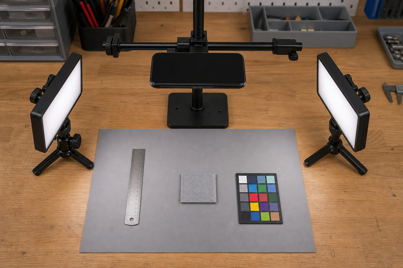
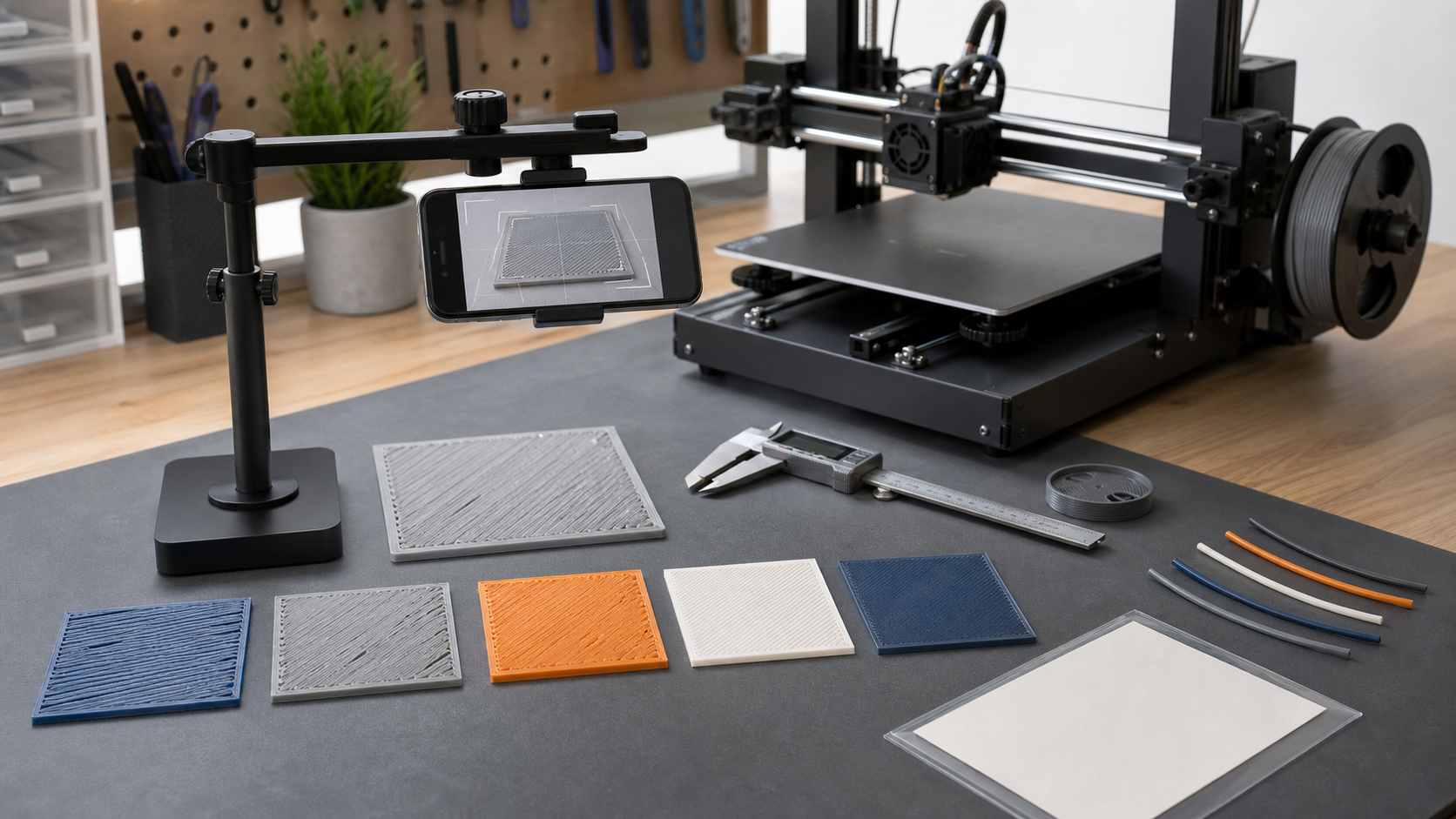
Consistency matters more than expensive equipment. A recent phone camera, a stable support, and controlled light are generally sufficient. The camera should face the sample as squarely as possible so that one edge is not noticeably larger than the opposite edge.
Place the sample on a neutral, nonreflective background. Mid-gray card works well for pale, dark, and brightly colored filament. Pure white backgrounds can cause dark samples to be overexposed, while black backgrounds may hide fine strings or dark edges.
Use a phone stand, copy stand, or fixed overhead arm. Handheld photographs introduce small changes in distance and angle that make side-by-side comparisons harder. If the camera application offers a grid, use it to align the test square with the frame.
Use Light That Shows Texture
Flat frontal light can conceal the ridges you are trying to document. A light placed at a shallow angle creates small shadows along extrusion lines and makes surface height changes easier to see. However, one strongly directional lamp can exaggerate defects or produce distracting glare.
A practical arrangement uses two soft lights:
- Position the main light roughly 30 to 45 degrees above the sample and slightly to one side.
- Place a weaker fill light on the opposite side.
- Rotate the sample until line texture is visible without broad white reflections.
- Keep the light positions marked on the desk for future sessions.
For glossy filament, diffuse the lights with proper photographic diffusion material or bounce them from a pale wall. Avoid placing paper or improvised plastic against hot lamps.
Capture one standard overhead view and, when needed, one low oblique view. The overhead image is best for line spacing and regional comparison. The oblique image emphasizes ridges, lifted edges, and buckling. Do not substitute one for the other; they answer different questions.
Lock Focus and Exposure
Automatic camera adjustments can make identical samples appear different. A black calibration square may cause the camera to increase exposure, while a white square may cause it to reduce exposure. If the camera supports focus and exposure locking, set them using the sample area and retain the same settings for a comparison series.
Avoid digital zoom. Move the camera closer while staying within its reliable focusing distance, or capture at full resolution and crop later. Check the first image at high magnification before photographing an entire batch. Extrusion lines should have distinct edges rather than a soft, painted appearance produced by missed focus or aggressive noise reduction.
Add Scale and Identity Without Hiding the Sample
A photograph becomes less useful when its origin is uncertain. Include a small identifier beside the print, but keep it outside the diagnostic area. A reusable card can carry a short printer code and test number. Detailed settings can remain in the file name or accompanying record rather than filling the photograph with notes.
Include a ruler or scale marker when physical dimensions matter. Place it on the same plane as the sample; a ruler several centimeters below or above the print introduces perspective error. The scale is a reference, not a substitute for caliper measurements.
A compact identification scheme might use:
printer-region-material-offset-attempt
For example, a file stem such as p03-center-pla-zm005-t02 can identify printer 03, the center bed region, PLA, a minus 0.05 millimeter offset, and the second attempt. Keep a short key with the archive so that codes remain understandable to other operators.
Avoid embedding every fact only in the file name. File names are easily shortened, reordered, or detached from their original folders. A durable record combines a useful name with a calibration sheet or small CSV log.
Capture a Minimum Diagnostic Set
A complete session does not require dozens of photographs. It requires a predictable set that answers the likely maintenance questions.
For each calibration condition, capture:
- One uncropped overhead image
- One close overhead image of the most informative region
- One oblique image if ridges, lifting, or surface damage are present
- One image of the underside after removal when it adds evidence
- One contextual image showing the sample position on the build plate for regional problems
The contextual photograph is especially valuable when a five-point test fails in only one corner. Photograph it before removing the pieces. Once individual squares are detached, their original positions can be confused or accidentally rotated.
Do not photograph only the worst result. A known-good first layer provides the baseline that makes later defect images interpretable. Create a reference sheet after commissioning a printer, installing a new build surface, changing nozzle size, or completing major motion-system maintenance.
Crop and Normalize Images Carefully
Editing should make comparisons easier without erasing evidence. Start from a copy of the original and preserve the unedited capture in the session folder.
Crop every standard view to the same aspect ratio. Leave a narrow border around the sample so lifted edges and stray extrusion remain visible. If multiple photographs need identical pixel dimensions, use the image resizer after cropping. Matching dimensions help comparison images align cleanly in documents and maintenance tickets.
Rotation is appropriate when it corrects a small camera alignment error. Strong perspective correction should be used cautiously because it resamples the image and can alter the apparent spacing of fine lines. A visibly skewed photograph is usually better recaptured with the camera level.
Keep color adjustments restrained. Correct an obvious color cast using the neutral background as a guide, but do not increase contrast until gaps disappear into black shadows or highlights clip to white. Sharpening can make extrusion edges easier to inspect, yet excessive sharpening creates halos that resemble thin gaps.
An AI editor can be useful for removing an irrelevant object at the edge of a contextual photograph or extending a plain background. It should not reconstruct, smooth, or replace any part of the printed sample. Diagnostic pixels are evidence. If a cleanup is genuinely helpful, perform it with the AI photo editor on a derivative copy and label that version as edited.
Preserve Thin Lines During Compression
First-layer photographs contain repeated high-frequency detail. Fine parallel lines, tiny gaps, and sharp texture transitions are exactly the features that aggressive compression can damage. Block artifacts may bridge a real gap, while ringing can create a false bright edge beside an extrusion line.
Choose the output format according to the record’s purpose:
| Use | Suggested format | Reason |
|---|---|---|
| Archival source | Original camera format or high-quality JPEG | Retains the fullest available capture detail |
| Annotated diagnostic crop | PNG | Preserves thin marks and flat annotation graphics cleanly |
| Compact sheet photograph | High-quality JPEG or WebP | Reduces document size when settings remain conservative |
| Transparent isolated sample | PNG or WebP with alpha | Supports overlays, though isolation may remove contextual evidence |
Inspect compressed results at 100 percent magnification. Compare the same area in the original and derivative, concentrating on the narrowest gaps and the edges of glossy lines. If compression changes what you would diagnose, the file is too small.
The image compressor can reduce sharing size after the images have been cropped. Keep the high-detail originals separately and compress only the copies intended for reports, messages, or issue trackers.
Assemble a Compact Calibration Sheet
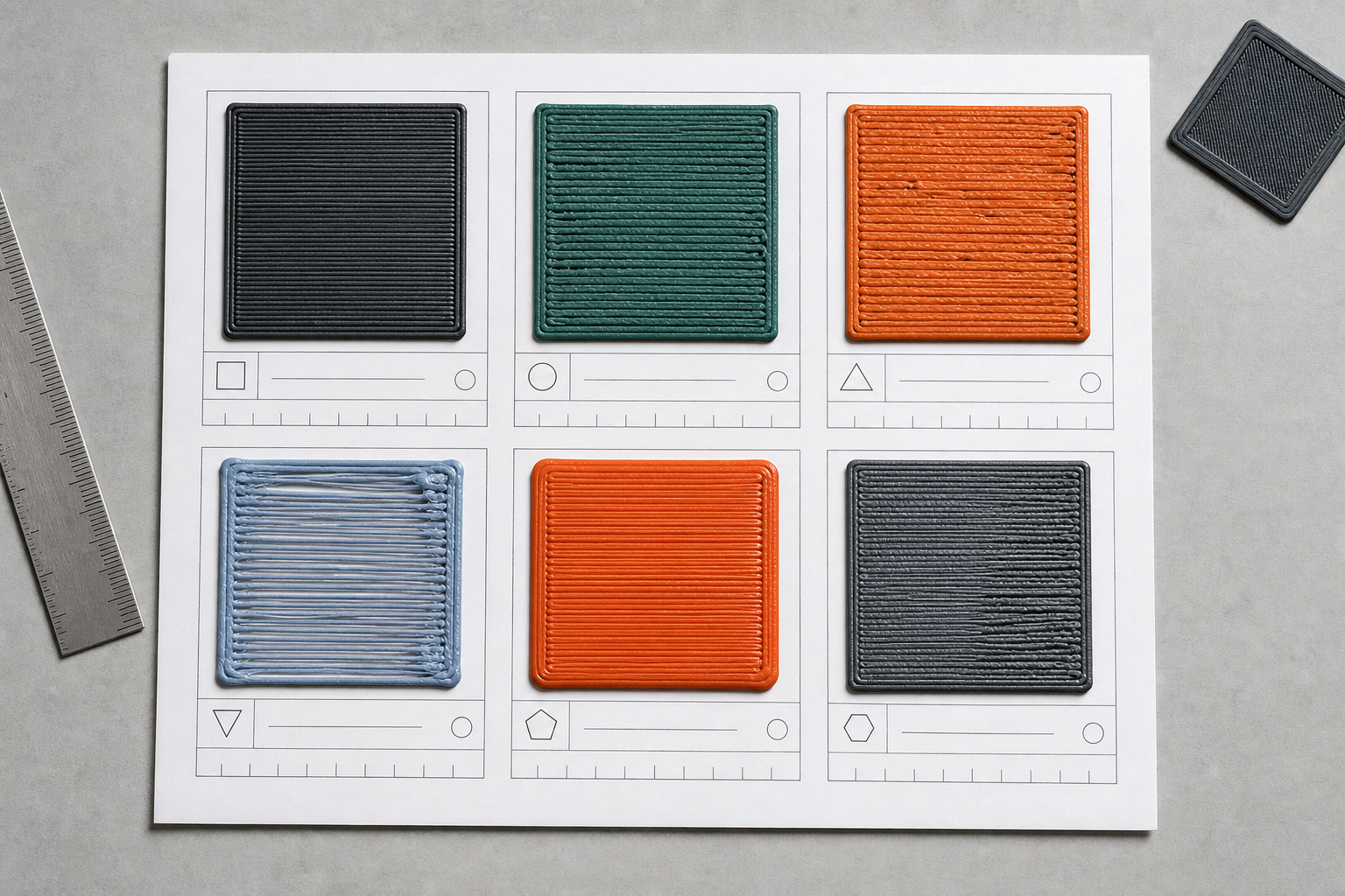
A contact-style calibration sheet makes separate photographs easier to scan. Use a consistent grid with equal image sizes and enough room for short metadata fields. Do not shrink six or eight samples so far that extrusion lines become indistinct when the page is viewed at normal size.
A useful one-page sheet can contain:
- Printer identifier and session date
- Nozzle diameter and material family
- Build surface type
- Fixed slicer settings shared by all tests
- Four to six aligned sample images
- One changing variable beneath each image
- A brief observation and next action
For a nozzle-offset series, arrange images from the highest nozzle position to the lowest. For a bed-region test, place images in a grid corresponding to their actual positions on the printer. Spatial arrangement reduces the risk of mixing up front, rear, left, and right samples.
If annotations are necessary, use simple arrows or circles placed beside the relevant line defect. Keep an untouched version of the photograph. An annotation should direct attention, not cover the boundary being examined.
After preparing the page images, combine them with the image-to-PDF tool. PDF is convenient for attaching a fixed calibration record to a service ticket, printer log, or shared maintenance folder. Verify the resulting page at normal viewing size and at high zoom before distributing it.
Use a Decision Table for First Comparisons
A photo sheet is most effective when observations are separated from conclusions. Describe what is visible first, then list plausible causes and the next controlled test.
| Visible pattern | Plausible interpretation | Next controlled check |
|---|---|---|
| Clear gaps between lines across the whole square | Nozzle may be too high or first-layer flow may be low | Make one small offset change while holding flow constant |
| Raised ridges with a rough upper face | Nozzle may be too close or material may be overextruded | Raise the nozzle slightly and repeat the same model |
| Good center with weak bonding in one corner | Local bed-height, mesh, contamination, or surface issue | Clean the region and repeat a positional test |
| Lines begin well but tear later | Debris, inconsistent extrusion, temperature instability, or dragging | Inspect nozzle condition and review the print sequence |
| One edge curls while the rest remains flat | Local adhesion, cooling, contamination, or thermal effects | Repeat after controlled cleaning without changing offset |
| Appearance changes only with one filament spool | Material condition or dimensional variation may contribute | Test a known reference material using the same settings |
These are starting hypotheses, not universal diagnoses. Printer mechanics, firmware behavior, sensing systems, surface coatings, and filament properties all affect the result. The value of the sheet is that it shows which observation led to the next test.
Organize Records So They Remain Searchable
Store each session in a folder whose name sorts chronologically, such as 2026-07-20_p03_first-layer. Within it, keep originals, edited derivatives, the final PDF, and a short settings record in separate locations.
A simple structure is sufficient:
originalsfor untouched camera filescropsfor normalized comparison imagesreportfor the final PDF and notesprojectfor slicer files or exported settings when appropriate
Record changes to hardware as well as slicer values. A perfect reference made before replacing a nozzle may not remain an appropriate baseline afterward. The same applies to a new magnetic sheet, changed spacers, rebuilt hot end, firmware update, or revised bed mesh.
Use retention rules that match the environment. A home operator may keep only a known-good reference and the latest troubleshooting series. A shared lab may benefit from retaining records around repairs and recurring failures. The point is not to archive every square forever, but to preserve enough evidence to compare printer states.
Run a Final Evidence Check
Before considering the sheet complete, review it as if you had not been present during the test.
Confirm that:
- The printer and material can be identified.
- The sample orientation or bed position is unambiguous.
- The changing variable is stated for every comparison.
- Images use consistent framing and direction.
- Highlights do not obscure extrusion lines.
- Compression has not bridged gaps or created false edges.
- Edited versions are distinguishable from originals.
- The known-good reference is clearly identified.
- The next maintenance action follows from a visible observation.
- The PDF remains readable on an ordinary laptop screen.
A strong first-layer photo sheet does not need elaborate design. Its value comes from repeatability and restraint. When the camera position, lighting, naming, edits, and test conditions remain controlled, a flimsy calibration square becomes a durable record of printer behavior. That record can shorten future troubleshooting, improve handoffs between operators, and make maintenance decisions easier to explain.